:sales@zsjhsteel.com WhatsApp:+86-15122582058


Views: 0 Author: Site Editor Publish Time: 2026-09-23 Origin: Site


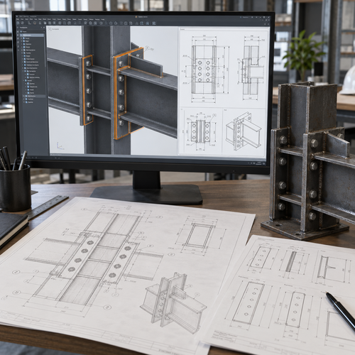
For a steel fabricator, a three-dimensional model is valuable only when it helps convert approved design intent into clear, controlled production information. Tekla Structures supports this transition by bringing members, plates, bolts, welds, openings and assembly relationships into one coordinated model. From that model, the detailing team can prepare the drawings and material data required for fabrication, review and site erection.
ZSJH combines Tekla Structures with structural design, calculation, BIM detailing and manufacturing experience. The software provides a shared technical environment, while ZSJH engineers remain responsible for reviewing the design basis, resolving interfaces, checking constructability and issuing only approved information to the factory.
Model Function | Practical Fabrication Value |
Detailed member geometry | Represents beams, columns, trusses, braces, plates and profiles with fabrication-level dimensions. |
Connections and interfaces | Coordinates bolts, welds, end plates, stiffeners, base plates, openings and adjacent components. |
Drawing generation | Supports general arrangement, assembly, single-part and erection drawings based on the coordinated model. |
Part and assembly numbering | Helps identify repeated components and links model objects with drawing marks and production records. |
Material information | Supports quantity takeoff and bills of materials for procurement, cutting, packing and project control. |
Revision coordination | Allows changes to be reflected across related model objects and outputs, subject to checking and approval. |
Data exchange | Enables agreed model and drawing exchanges with designers, clients and downstream systems where compatible interfaces are included in the project scope. |
Tekla does not make incomplete design information correct automatically. Load criteria, member design, connection responsibility, material grades, tolerances and inspection requirements must still be defined and verified by qualified project personnel.
1. Receive and register project information. ZSJH collects the current structural, architectural and interface drawings together with design notes, standards, material requirements and revision status.
2. Review the design basis. The technical department checks grids, levels, member sizes, loads, interfaces and the completeness of the supplied package. Missing information is clarified with the client.
3. Set up the model. Project coordinates, grids, levels, profiles, material grades and agreed naming rules are established before detailed modeling begins.
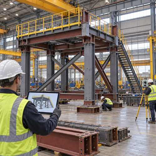
4. Model the primary and secondary steelwork. Beams, columns, trusses, bracing, platforms, stairs, walkways, equipment frames and other scope items are developed to the required level of detail.
5. Detail connections and components. Plates, stiffeners, bolts, welds, holes, cuts, edge distances and erection interfaces are added according to the approved design and applicable standards.
6. Check coordination and constructability. The team reviews collisions, access for bolts and welding, member clearances, transport splits, erection needs and factory capabilities.
7. Produce controlled outputs. General arrangement drawings, assembly drawings, single-part drawings, erection drawings, member marks and bills of materials are prepared as required by the contract.
8. Complete internal checking. ZSJH engineers compare drawings and schedules with the model, design basis and project requirements before client submission.
9. Submit, revise and obtain approval. Client markups are incorporated through controlled revisions until the agreed Approved for Fabrication status is issued.
10. Support fabrication and changes. The factory works from the released revision. Any later issue is coordinated by the assigned project contact and handled through the approved change process.
ZSJH can quote and manufacture the full range of steel structure products listed on its website. For focused project enquiries, Tekla-based examples are especially relevant to these five business areas:
· Industrial factories and warehouses, where repeated frames, bracing, crane interfaces and erection sequences require consistent member information.
· Heavy steel structures, where large built-up members, thick plates, complex nodes and transport splits benefit from three-dimensional coordination.
· Equipment support structures and industrial equipment frames, where steelwork must coordinate closely with machinery, platforms, access and piping zones.
· Steel beams, columns and trusses, where part marks, connection details, hole positions and assembly drawings directly support workshop production.
· Non-standard steel components, where irregular geometry and project-specific interfaces need to be communicated clearly before fabrication.
Other available scopes include commercial steel structures, steel residences, platforms, stairs, walkways, bridge steel components and modular buildings. The selected detailing level and deliverables depend on the contract and project requirements.
The model and drawings must use the material grades and standards approved for the project. Common ZSJH capabilities include the following examples:
System | Common Examples | Typical Application |
GB | Q235B, Q355B, Q355NH; building structural plate Q235GJ-Q690GJ; bridge plate Q355q-Q690q; Z15/Z25/Z35 through-thickness plate | Domestic and Chinese-led overseas projects; special grades as required |
ASTM | A36, A572 Gr50 and A992; A325/A490 high-strength bolts | North American and international EPC projects |
EN | S235JR, S355JR and S355NL | European and project-specified work |
JIS | SS400, SM490A/B and SN490B | Japanese and Southeast Asian projects |
Welding consumables | AWS A5.1 E70xx, JIS Z3312 YGW11 and GB/T 5117 | Selected to match the approved welding procedure and base material |
Typical design references may include AISC 360 and ASCE 7, EN 1993 and EN 1991, SNI 1726:2019 and SNI 1727:2020, or GB 50017-2017, GB 50009-2012 and GB 50011-2010 (2016 edition). Welding requirements can be specified under AWS D1.1/D1.1M, AWS D1.5, EN ISO 3834, EN ISO 9606-1 or GB 50661-2011, depending on the project. ZSJH can manufacture to customer-specified standards after technical review and contract confirmation.
A coordinated model establishes the intended dimensions, marks and relationships, but physical fabrication still requires documented inspection. ZSJH can provide material certificates and welding inspection reports and can support third-party inspection when required.
Control Area | Typical Method | How Model Information Helps |
Weld inspection | VT for all applicable welds; UT, MT, PT, RT or ET where specified | Drawings identify weld type, size and location; the inspection plan defines the required method and extent. |
Dimensions | Verified tapes, calipers, weld gauges, total station and other suitable instruments | Member geometry, hole positions, plate locations and assembly dimensions provide inspection references. |
Surface preparation | Sa 2, Sa 2.5, Sa 3, St 2/St 3 or pickling as specified | Drawings and coating schedules identify the required treatment by component or area. |
Coating | Dry-film-thickness gauge and project acceptance criteria | Component marks support traceability between the coating record and fabricated item. |
Material traceability | Mill certificates, heat or batch references and material records | Part marks and BOM data help maintain the link between specified material and fabricated components. |
ZSJH may use typical internal checks such as overall length within ±3 mm, section dimensions within ±1-2 mm, hole position within ±1.5 mm, member bow of L/1000 and not more than 5 mm, or plate position within ±3 mm. These values are not universal acceptance limits. The approved drawings, contract, governing code and agreed inspection plan always take precedence.
· Structural analysis and member design under the governing code
· A clearly defined design basis and connection responsibility
· Engineering review of changes, loads and interfaces
· Client review and written approval before fabrication release
· Qualified welding procedures, personnel and physical inspection
· Factory workmanship, calibration, traceability and production control
The main benefit is controlled coordination: one detailed model can support many related outputs. The quality of those outputs still depends on accurate inputs, competent engineering, disciplined revision control and verification in the factory.
Can ZSJH detail a project when the client has no complete structural drawings?
Yes. ZSJH can provide structural design, structural calculation and BIM detailing services. The required design inputs and responsibilities must be agreed before fabrication information is released.
Does a Tekla model eliminate drawing review?
No. The model and generated outputs require internal checking, client review where applicable and controlled approval before fabrication.
Can ZSJH provide BOMs and fabrication drawings?
Yes, when included in the agreed scope. Deliverables can include model data, general arrangements, assembly drawings, single-part drawings, erection drawings and material lists.
Can ZSJH follow international standards?
Yes. ZSJH can work with commonly used GB, ASTM/AISC/AWS, EN and JIS requirements and customer-specified standards after project review.
Can third-party inspection be arranged?
Yes. ZSJH supports third-party inspection and can provide agreed quality records, including material certificates and welding inspection reports.
If you need steel detailing, shop drawings or fabrication support for a factory, warehouse, heavy steel structure, equipment frame or custom steel component, send ZSJH your available drawings and project requirements. Our technical team can review the design basis, identify missing information and define the appropriate modeling, approval and manufacturing workflow.


