Ultrasonic testing (UT) and radiographic testing (RT) can examine weld interiors without cutting the component apart. Both are useful in structural steel fabrication, but they reveal discontinuities in different ways. For buyers of built-up beams, plate girders and welded columns, the best choice follows the joint design and inspection specification rather than a claim that one method is always superior.
How ultrasonic weld testing works
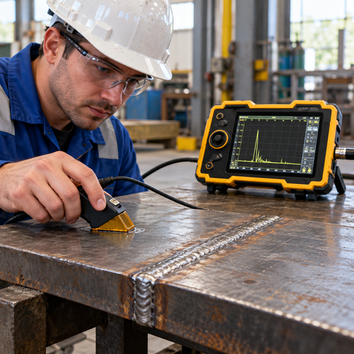
UT introduces high-frequency sound into the steel and evaluates returned signals. Conventional weld testing commonly uses an angle-beam probe, couplant and a planned scan over accessible steel beside the weld. With a suitable procedure, the examiner can assess the location and response of internal discontinuities. Probe angle, flaw orientation and joint geometry affect detection.
UT can be useful for thicker sections and some examinations with access from one surface. It is often well suited to detecting planar discontinuities when the sound beam is correctly directed. Surface condition, material structure and operator technique can limit performance. “Thick steel” alone is not enough information to specify the scan.
Fig 1 Ultrasonic Testing Angle Probe on a Steel Butt Weld
How radiographic weld testing works
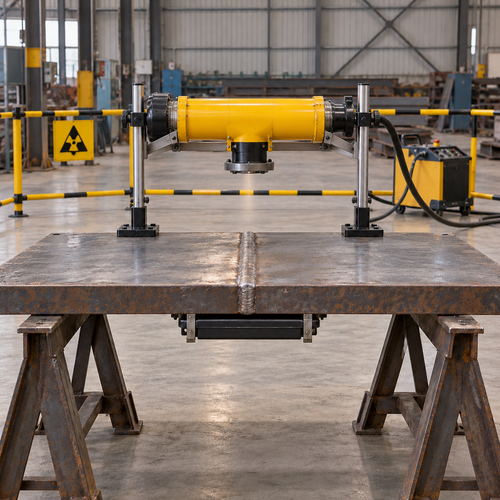
RT passes X-rays or gamma radiation through the component and records the resulting image on film or a digital detector. Variations in radiation transmission can show internal discontinuities. The image provides a record that can be reviewed later, but it is a projection rather than a complete three-dimensional model of the weld.
RT can give useful images of volumetric discontinuities such as porosity and some inclusions. Tight planar flaws may be difficult to reveal when their orientation is unfavourable to the radiation beam. Source positioning, thickness and access for the source and detector affect the technique. Exposure requires controlled radiation protection arrangements and qualified personnel.
Fig 2 Radiographic Testing Setup for a Steel Plate Butt Weld
Compare the practical differences
Factor
UT
RT
Physical principle
Sound-wave response
Radiation transmission image
Typical strength
Planar flaws with suitable beam direction
Volumetric indications with suitable exposure
Access
Probe scanning surface; sometimes one-surface access
Source and detector positioning required
Records
Report; stored data if technique provides it
Film or digital image and report
Work planning
Coupling and scan coverage
Controlled radiation arrangements
Neither method reliably finds every discontinuity in every joint. UT can provide useful positional information, while RT makes some internal patterns easier to visualize. A successful UT examination does not automatically satisfy a separate RT requirement. Likewise, an acceptable radiograph does not replace required UT. Any substitution needs approval under the governing project requirements.
Define the scope before fabrication
Provide a weld map or marked drawings identifying the joints, material grades, thicknesses and weld preparation. State the testing method, examination extent, applicable procedure and acceptance criteria. A partial-penetration groove weld, a fillet weld and a complete-joint-penetration butt weld should not be treated as interchangeable examination targets. Their geometry and design purpose change the inspection problem.
Clarify whether the scope means every specified weld, selected joints or defined weld lengths. A percentage without an agreed sampling basis can be interpreted differently by the fabricator, inspection agency and buyer. There is no single UT or RT percentage that applies to all overseas structural steel orders. Specify how unacceptable findings affect additional examination and repair.
Check timing and records
The inspection plan should define surface preparation, access and final examination timing. Where delayed cracking is a concern, follow the hold time required by the applicable documents. Do not use immediate post-weld testing as the only release check when a later final examination is specified.
Request reports linked to component and weld numbers. For UT, retain the procedure, examined coverage, equipment and calibration references, indication locations and evaluation. For RT, retain the technique and image identification, examined coverage, required image-quality verification and evaluation. Record limitations and repaired areas. Saved UT data depend on the technique and recording arrangement; not every conventional UT report includes a stored scan.
Inspection workflow
Review drawings and joints → approve method and coverage → prepare access and confirm timing → perform UT or RT → evaluate and document → approved repair and re-examination if needed → inspection release
Coordinate weld NDT with ZSJH Steel
Send ZSJH Steel the drawings, steel grades, plate thicknesses, weld map, required UT or RT scope, acceptance standard and delivery destination. We can coordinate fabrication and inspection requirements, including agreed third-party witnessing. Defining the NDT package early helps reserve inspection access, plan customer review and avoid preventable delays before coating or shipment.

 English
 العربية
 Français
 Русский
 Español
 Português
 Deutsch
 italiano
 日本語
 한국어
 Nederlands
 Tiếng Việt
 ไทย
 Polski
 Türkçe
 አማርኛ
 ພາສາລາວ
 ភាសាខ្មែរ
 Bahasa Melayu
 ဗမာစာ
 தமிழ்
 Filipino
 Bahasa Indonesia
 magyar
 Română
 Čeština
 қазақ
 हिन्दी
 فارسی
 Kiswahili
 اردو
 Gaeilge
 Māori
 Hausa
 Igbo
 Kurdî
 Lëtzebuergesch
 ਪੰਜਾਬੀ
 Runasimi
 Yorùbá
 isiZulu