1 Product Introduction
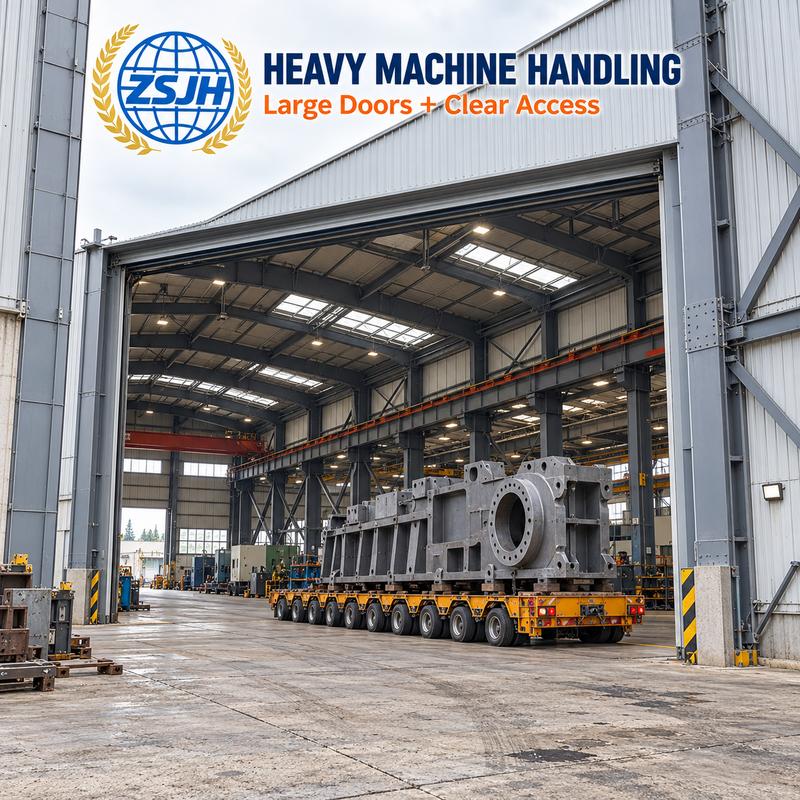
Built around heavy equipment, lifting operations and large-component movement. ZSJH Steel supplies custom workshop steelwork with coordinated load paths, crane-support options and transport splices, supported by structural design, shop detailing, fabrication inspection and export packing.
2 Separate the Loads Before Sizing the Frame
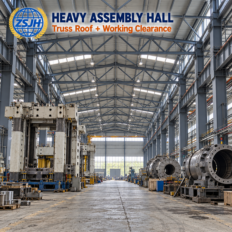
A heavy workshop may contain floor-mounted machines, crane runway supports and elevated maintenance platforms. List each load at its actual support point. Machine weight carried by an independent foundation should not be treated as a roof load, while a frame-supported pipe rack must be included in the building design.
For operating equipment, submit supplier reactions and relevant dynamic data. For cranes, provide rated capacity, span, wheel reactions, horizontal actions, working duty and rail elevation. Rated lifting capacity alone is insufficient to define runway supports.
Load source | Required information | Interface |
Production machinery | Operating reactions and anchorage positions | Independent foundation or specified frame support |
Overhead crane | Wheel reactions, duty and rail geometry | Runway beams, corbels and columns |
Maintenance platform | Equipment and access loads | Platform beams and connections |
Roof attachments | Locations and support reactions | Roof members and designated connections |
3 Select Members and Splices Together
3.1 Built-up H-section members, box members or trusses may be selected through analysis. Corbels, stiffeners and bracing form part of the load path. Steel grade, section geometry and connection details are considered together; higher strength alone does not resolve stiffness or fatigue requirements.
3.2 Compare 6 / 9 / 12 / 18 m bays against the production layout. Required clear spans, heights and plate thicknesses follow the engineered scheme rather than a universal heavy-duty size. Q355B, S355 or ASTM A572 Grade 50 may be specified; substitutions require approval.
3.3 Review the maximum transport envelope and site lifting capacity before detailing splices. Confirm piece weights, connection access and the erection sequence so oversized assemblies do not arrive without a workable installation plan.
4 Inspect the Locations That Control Assembly
4.1 For built-up members, check section geometry and straightness. For crane-supported frames, verify corbel positions and runway connection holes against the approved drawings. For segmented members, agree fit checks or trial assembly where required.
4.2 SAW, FCAW or GMAW follow the approved welding procedure. Specify the applicable acceptance code, such as AWS D1.1 or GB 50661, and the welds requiring UT or MT. EN ISO 3834 addresses welding quality management. Confirm inspection records and any third-party witness points before manufacture.
4.3 Coating selection follows process exposure and delivery conditions. Verify surface preparation and specified dry-film thickness; fire protection requires a separate specification.
5 Release and Deliver by Erection Zone
Load data confirmation → Frame and runway coordination → Transport segmentation → Shop drawing approval → Cutting and built-up welding → Straightening and drilling → Inspection → Surface protection → Zone-marked packing → Planned erection.
6 Frequently Asked Questions
Q1 Is every heavy workshop supplied with a crane bay?
No. Crane support is included only when specified. Confirm whether lifting uses overhead cranes, mobile equipment or another system before reserving runway steel.
Q2 Can the workshop be sized for future heavier cranes?
Future crane data must be included in the design brief. Existing supports cannot be assumed suitable for an upgrade without review.
Q3 How are oversized members shipped?
Members may be segmented to suit the transport route and site lifting equipment. Splices and the erection method require approval before fabrication.
Q4Can you work from incomplete structural drawings?
ZSJH can support design and detailing, but machinery and crane supplier data must be confirmed for the affected design.
7 Request Your Proposal
Send your drawings to ZSJHSTEEL for a tailored quotation. From Tekla detailing to fabrication and export coordination, we support your next project and long-term supply needs

 English
 العربية
 Français
 Русский
 Español
 Português
 Deutsch
 italiano
 日本語
 한국어
 Nederlands
 Tiếng Việt
 ไทย
 Polski
 Türkçe
 አማርኛ
 ພາສາລາວ
 ភាសាខ្មែរ
 Bahasa Melayu
 ဗမာစာ
 தமிழ்
 Filipino
 Bahasa Indonesia
 magyar
 Română
 Čeština
 қазақ
 हिन्दी
 فارسی
 Kiswahili
 اردو
 Gaeilge
 Māori
 Hausa
 Igbo
 Kurdî
 Lëtzebuergesch
 ਪੰਜਾਬੀ
 Runasimi
 Yorùbá
 isiZulu


