:sales@zsjhsteel.com WhatsApp:+86-15122582058


ZSJH


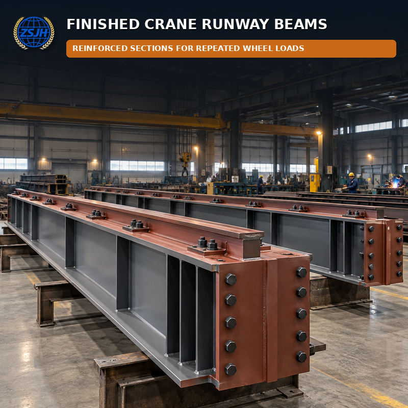
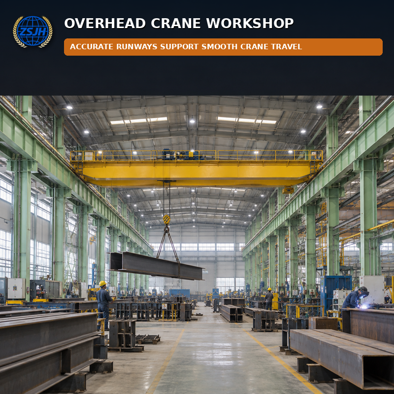
Industrial Steel Crane Beams support the rails and wheel loads of overhead travelling cranes. In addition to vertical bending, runway beams may be designed for horizontal surge, torsion, fatigue and concentrated wheel reactions. Accurate rail-seat geometry, stiffener positions, splice alignment and support interfaces are essential for reliable crane operation.
ZSJH Steel fabricates welded or reinforced crane runway beams for workshops, manufacturing plants, warehouses, maintenance bays and heavy industrial facilities. Members can include bearing stiffeners, cap channels or plates, rail clips, brackets, end stops, walkway supports and bolted splices according to approved design drawings. Crane capacity and runway engineering remain the responsibility of the project designer; fabrication is performed to the released documents.
Item | Available Options |
Beam Type | Welded H/plate girder or reinforced rolled section |
Duty | Project-defined crane class, wheel loads and fatigue category |
Rail Support | Cap plate, channel, rail seat and clip-hole arrangement |
Reinforcement | Bearing stiffeners, web stiffeners and local flange reinforcement |
Splices | Shop welds or aligned bolted field splices |
Attachments | Brackets, end stops, walkway and service supports |
Accuracy | Controlled top elevation, sweep, camber and hole alignment |
Finish | Project-specified shop coating with protected contact surfaces |
• Fabricated for repeated moving loads and project-defined fatigue demands.
• Controlled top flange and rail-seat geometry supports runway alignment.
• Bearing stiffeners reinforce regions below wheel loads and column supports.
• Brackets, rail fixings and walkway attachments can be shop-fitted.
• Match-marked splices help maintain alignment between runway segments.
• Inspection records support traceable installation and commissioning files.
Manufacturing workshops; steel mills and foundries; warehouses and logistics centers; maintenance facilities; power plants; shipyards; precast and heavy assembly plants.
Options include beam section, steel grade, rail-seat detail, cap plate or channel, stiffener arrangement, end stops, splice positions, brackets, access platforms, camber, tolerances and coating. The fabrication review checks rail-axis references, column support levels, splice access and the relationship between left and right runway lines.
1. Review crane loading references, fatigue category and runway datum.
2. Verify material grades and critical plate traceability.
3. Cut, assemble and weld the main beam under controlled procedures.
4. Install bearing stiffeners, cap plates, brackets and end details.
5. Drill splice and rail-fixing holes from coordinated datums.
6. Straighten and verify top-flange level, sweep and camber.
7. Inspect critical welds and check mating splice assemblies.
8. Protect contact surfaces, coat, match-mark and pack by runway line.
Crane beams are tagged by runway line, grid and erection sequence. Rail seats and splice faces are protected from coating contamination or impact as required. Loose rail clips, bolts and accessories can be packed and labeled for the corresponding beam segment.
Do you design the crane runway system?
We can support drawing review and fabrication detailing, while the final structural design, crane loads and service classification must be confirmed by the project’s qualified engineer.
Can rail support plates and clip holes be prefabricated?
Yes. They can be shop-fitted or drilled to coordinated rail and beam drawings.
How do you control runway alignment?
We use common datums for rail seats, splices and support interfaces, then record key dimensions before release.
Provide the crane runway drawings, wheel-load data, rail details and required standards for a fabrication quotation.


